 |
|

5 Cabling
This is always the hardest part of this kind of problem. We had only a dozen or so cables/headshells to build, and we already had a collection of the appropriate crimping tools and hardware, so we did it ourselves. But if you are not set up for this, or you have a large number of cables to make, then you might consider getting some cables custom made. Look in the yellow pages, there are a surprising number of places that do this! Getting custom-made cabling is good, and you can get much more professional results, but can be expensive. For example, the RJ-45 to DB-25 adapter kits described below are about $10 each; custom-made headshells are about twice that (and take a couple of weeks to arrive). Similarly, crimping custom RJ-45 to RJ-45 leads is quite cheap (say, $5 each) but it takes a fair amount of time. Custom made RJ-45 socket to RJ-45 plug converters cost about $25 each.
We have settled on RJ-45 Cat-V cabling for all our office and computer room cabling needs. This included patching between racks in the computer room. For serial connections, we use patchable headshells that have RJ-45 sockets on the back. This allows us to patch whatever RJ-45-DB-25 connections we need.
Which is just as well, because there are many incompatible ways to represent serial connections on the RJ-45 plug. So the cabling has to be very careful to use the right mapping.
5.1 RJ-45 colors
RJ-45 cables and plugs have 8 pins/conductors. These are used as 4 matched pairs. There are a couple of conventions about how the pairs are mapped onto pins, but 100baseT uses the most common (known as EIA 586B). There are three common color-coding conventions for the individual conductors in RJ-45 cables. They are:
Table 1.
| Pin | Scheme 1 | Scheme 2 (EIA 568B) | Scheme 3 (EIA 568A) | Pair |
|---|---|---|---|---|
| 1 | Blue | White+Green | White+Orange | 2+ |
| 2 | Orange | Green | Orange | 2- |
| 3 | Black | White+Orange | White+Green | 3+ |
| 4 | Red | Blue | Blue | 1+ |
| 5 | Green | White+Blue | White+Blue | 1- |
| 6 | Yellow | Orange | Green | 3- |
| 7 | Brown | White+Brown | White+Brown | 4+ |
| 8 | White or Grey | Brown | Brown | 4- |
Note EIA 468A and EIA 568B are very similar, simply swapping the colors assigned to pair 2 and pair 3.
See for example the Cabletron Tech Support Site for more details.
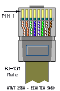
The pins in the RJ-45 plug are numbered from 1 to 8. Holding a patch lead with the cable pointing down and the clip away from you, pin 1 is at the left. Or, looking into an RJ-45 socket with the clip to the top, pin 1 is on the right. The following illustration (shamelessly lifted from the Cabletron web site above) shows it pretty well:
We have four classes of equipment to deal with in our setup:
- Sun servers
-
Sun servers operate as DTE (i.e. send data on TxD and read RxD, and assert DTR) with a female DB-25 socket on board. So we need to create a headshell for the Stallion that operates as DCE and has a male DB-25 plug (i.e. acts as a “null modem” cable as well as converts from RJ-45 to DB-25). We use headshells that have an RJ-45 socket in them and 8 short flyleads with DB-25 pins on the end. These pins can be inserted into the DB-25 plug as required. This allows us to create a custom RJ-45-DB-25 mapping. We used a couple of different sorts, including the MOD-TAP part no. 06-9888-999-00 and the FA730 series from Black Box.
On our version of the headshells, these flyleads had the following colours (from Pin 1-8): Blue, Orange, Black, Red, Green, Yellow, Brown, White. (Looking into an RJ-45 socket, with the clip towards the top, pin 1 is on the right.) This is how they are connected to the DB-25 socket:
Table 2.
Stallion RJ-45 Pin Colour Signal Sun DB-25 Male Pin RS232 Signal 1 Blue DCD 20 DTR 2 Orange RTS 5 CTS 3 Black Chassis Gnd 1 Chassis Gnd 4 Red TxD 3 RxD 5 Green RxD 2 TxD 6 Yellow Signal Gnd 7 Signal Gnd 7 Brown CTS 4 RTS 8 White RTS 8 DCD Note that colours may be different for your cables/headshells. In particular, pin 8 may be grey instead of white.
Remember to label the headshell clearly, in a way that will not fade/fall off/rub off with time!
- Cisco 16xx/26xx/36xx Routers
-
I think that all Cisco gear that has RJ-45 console ports and runs IOS® will have the same cable requirements. But best to check first. We have tried this on 1600s and 2600s only.
Both the Stallion card and the 2600 have RJ-45 connections, but of course they are not compatible. So you need to crimp up a special RJ-45-RJ-45 cable. And this cable must be plugged in the right way round! We use normal RJ-45 flyleads from the router to the patch panel, then the special flylead from the patch panel to the Stallion card.
We built two special Stallion-Cisco leads by cutting in half a 2m flylead and crimping an RJ-45 with the appropriate pinouts to each free end. The original connector will be the Cisco end of the cable, the new crimped connector will be the Stallion end. Holding the RJ-45 connector on the flylead with the cable pointing down and the clip pointing away, this is the order of the colours of the cables in our flylead (pins 1-8, from L to R): white/green, green, white/orange, blue, white/blue, orange, white/brown, brown. For the Stallion end, trim and discard the brown/white+brown and green/white+green pairs. Then holding the RJ-45 plug in the same manner (cable down, clip away), the connections should be (from L to R): None, None, Blue, Orange, White/Orange, White/Blue, None, None, as shown:
Table 3.
Cisco RJ-45 Pin Colour Cisco Signal Stallion RJ-45 Pin Stallion Signal 1 White/Green RTS N/C 2 Green DTR N/C 3 White/Orange TxD 5 RxD 4 Blue Gnd 3 Gnd 5 White/Blue Gnd 6 Gnd 6 Orange RxD 4 TxD 7 White/Brown DSR N/C 8 Brown CTS N/C Note again that colours may be different for your cables/headshells.
Carefully label the cable, and each end of the cable, and test it. If it does not work, testing is really hard as they do not make RJ-45 serial line testers!
Let me state this more strongly: Be very sure that you label this cable in a way that is easily, instantly and permanently recognisable as a special cable and not easily confused with normal drop cables. Some suggestions (from Hugh Irvine):
-
Make them out of different coloured cable.
-
For marking the ends, clear heat-shrink tubing slipped over printed labels *before* putting on the connectors is the best way I have seen for marking what they are.
-
You can also use Panduit or similar tags that you put on with nylon tie straps, but I find the ink wears off the tags.
-
- Cisco Catalyst® switches
-
Astoundingly, the pinout on the console ports of the Catalyst switches is actually different to the pinout used on the 26xx-series Cisco hardware. I think the way to tell which is which is by considering the operating software. If it uses IOS, then the previous pinout is required. If it uses the switch software, then this pinout is required.
Fortunately, while the pinouts are different, the Catalyst pinout is simply a mirror image of the pinout for the 2600. Even more fortunately, the Ciscos (both Catalyst switches and 2600s) seem to ship with a special “rollover” cable, which is exactly what is required in this case. We use the rollover cable from the Catalyst switches to the patch panel, then the same cable as above for the 2600s from the patch panel to the Stallion card, and it all works just fine.
This rollover cable is an RJ-45-RJ-45 cable and is intended to be used with the shipped (hardwired) RJ-45 - DB-25 and RJ-45-DB-9 headshells for console connections. Ours are 2m long, either light blue or black, and are quite flat. Attempts to use them for 100baseT Ethernet will fail miserably! You can tell it is a rollover cable by holding both ends with the cable pointing down and the clip pointing away from you. Check the colour of the leads in each pin in the two connectors, they should be mirror images. (In our case, one goes grey-orange-black-red-green-yellow-blue-brown, the other brown-blue-yellow-green-red-black-orange-grey). This is a rollover cable.
If you do not have a rollover cable present, then you can use the same cable as for the 26xx except plug it in the other way around (i.e. original 8-pin plug goes into the Stallion, the new crimped plug with only 4 active wires goes into the Catalyst switch).
- FreeBSD servers (or any other i386™ PC systems using a serial console)
-
We run FreeBSD 4 on a couple of i386 PCs for various peripheral uses. FreeBSD usually uses a screen and keyboard for the console, but can be configured to use a serial port (usually the first serial port known as COM1 in DOS/Windows® or ttyd0 in UNIX®).
The cabling for these servers depends on the PC harware. If the PC has DB-25 female socket on board (as most older PCs do), then the same headshell as works for the Sun server above will work fine. If the PC has DB-9 male plug on board (as more recent PCs tend to do), then there are two choices. Either use a DB-9 to DB-25 converter (this is not recommended as it can lead to unreliable connections over the long term as the adapter is bumped/works loose), or build an RJ-45 to DB-9 cable as follows:
Table 4.
Stallion RJ-45 Pin Colour Signal PC DB-9 Female Pin RS232 Signal 1 Blue DCD 4 DTR 2 Orange RTS 8 CTS 3 Black Chassis Gnd N/C 4 Red TxD 2 RxD 5 Green RxD 3 TxD 6 Yellow Signal Gnd 5 Signal Gnd 7 Brown CTS 7 RTS 8 White RTS 1 DCD See Section 7 for tips on configuring FreeBSD to use a serial console.
This, and other documents, can be downloaded from ftp://ftp.FreeBSD.org/pub/FreeBSD/doc/.
For questions about FreeBSD, read the documentation before contacting <questions@FreeBSD.org>.
For questions about this documentation, e-mail <doc@FreeBSD.org>.
Hosting by: Hurra Communications Ltd.
Generated: 2007-01-26 17:58:38